
"Clamp" inside a wind turbine can mean three quite different products: a beam clamp that grips structural steel, a P-clamp that cushions a small pipe or cable, and a cable cleat that restrains heavy power cables against short-circuit forces. They are not interchangeable, and picking the wrong one is a common source of rework and in-service failure.
Wind turbine towers use three types of clamps: beam clamps (attach to structural steel for mounting cable trays and brackets), P-clamps/pipe clamps (cushion small pipes and cables against vibration), and cable cleats (restrain main power cables against short-circuit forces). These are not interchangeable. Cable cleats must be rated for the short-circuit current; P-clamps provide vibration isolation; beam clamps must match the beam flange geometry.
- Best for
- Engineers and procurement teams specifying the correct clamp type for tower cable management, conduit support, or hydraulic line routing inside the tower
- Not suitable for
- Main power cable short-circuit restraint using standard P-clamps — that requires rated cable cleats with documented short-circuit test evidence
- Selection steps
- 1 — Classify duty (structural / pipe-cable cushion / power cable restraint) → 2 — Measure cable or pipe OD → 3 — Select beam clamp / P-clamp / cable cleat → 4 — Confirm material for corrosion environment → 5 — Specify anti-vibration insert if required
- RFQ information
- Clamp type, cable or pipe OD, mounting surface details, corrosion environment, short-circuit rating if cable cleat required
§ 01 Why clamps matter in a tower
A wind turbine tower is a tall steel tube carrying power and control cables from the nacelle down to the base, plus instrumentation, conduits and equipment. All of it has to be supported against gravity, vibration, thermal movement and — for the main power cables — the violent electromagnetic forces of a short circuit. Clamps are the components that do this, and each clamp family is engineered for a particular duty.
§ 02 Beam clamps
A beam clamp grips the flange of a structural steel member (a beam, a platform edge, a bracket) to provide a fixing point without drilling or welding. Inside the nacelle and on tower platforms they are used to hang cable trays, mount equipment, and create anchor points. The load path is mechanical clamping onto the steel flange, so the key specifications are the flange thickness range, the safe working load, and the corrosion protection of the clamp body.
§ 03 P-clamps (cushioned clamps)
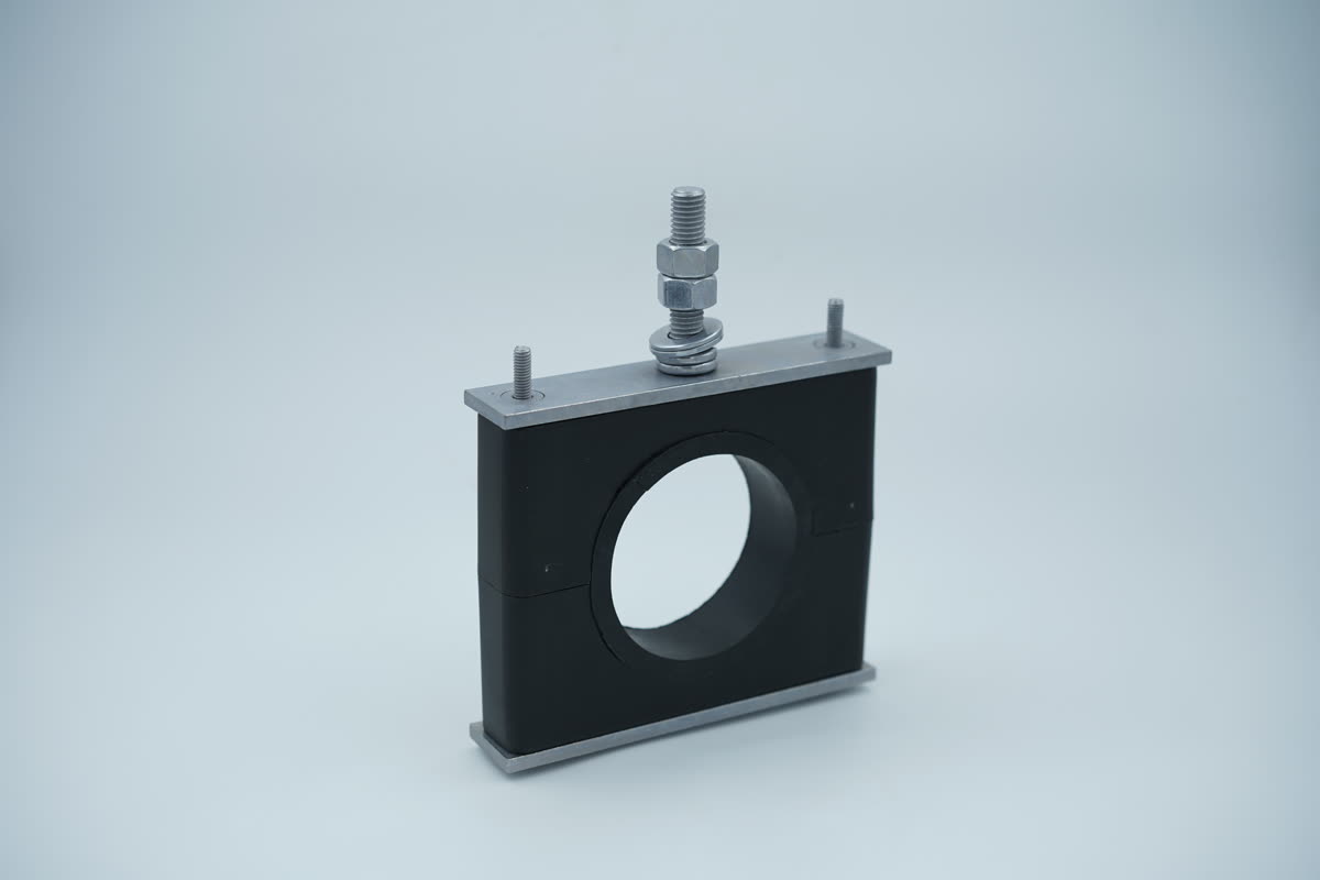
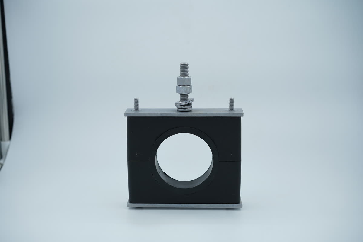
A P-clamp — named for its shape — is a single-bolt loop, usually lined with rubber or a polymer cushion, that secures an individual cable, conduit or small pipe to a surface. The cushion damps vibration and protects the cable jacket. They are everywhere in a turbine for routing control cables, hydraulic lines and small-bore pipework, but they are not rated to restrain heavy power cables under fault conditions.
§ 04 Cable cleats
A cable cleat is a load-rated restraint for power cables, designed to hold them in position and survive the peak electromagnetic force generated during a short circuit. Unlike a P-clamp, a cleat is sized and tested to IEC 61914 short-circuit ratings. In wind towers they secure the main LV/MV power cables along the descent, in trefoil or single formation. The underlying principles are covered in what is a cable cleat and the force they must withstand in short-circuit force.
§ 05 How to choose
| Clamp type | Secures | Rated for short circuit? | Typical location |
|---|---|---|---|
| Beam clamp | Trays / equipment to steel | n/a (structural fixing) | Nacelle, platforms |
| P-clamp | Single small cable / pipe | No | Control & hydraulic routing |
| Cable cleat | Power cables | Yes — IEC 61914 | Main power descent |
For offshore and coastal turbines, the clamp material matters as much as the type: marine atmospheres call for A4-80 (316) stainless or polymer bodies to resist corrosion — see 304 vs 316 stainless for offshore fasteners. Mixed-metal mountings should also be checked for galvanic corrosion.
Related: Earthing Clamps for Lightning Down-Conductors
Evidence and decision boundary
- Direct evidence
- IEC 61914 defines cable-cleat requirements and tests, while IEC 61400-1 and ISO 12100 provide design and risk context. No catalogue figure alone qualifies a tower cable route.
- Engineering inference
- Select by cable and formation, declared short-circuit restraint, load direction, substrate, vibration, bend control, environment, access and maintainability.
- Typical or indicative value
- Spacing, working load and life are project values until evidence matches the offered assembly and installation geometry.
Primary sources checked
- IEC 61914:2021 - cable cleats
- IEC 61400-1:2019 - wind turbine design requirements
- ISO 12100:2010 - machinery risk assessment
Related commercial route: Compare wind-turbine clamp systems and RFQ inputs.